 FR
FRPlastic Junction Box with KCD4 4-Pin 30A Waterproof Rocker Switch FILN Custom IP65


Détails du produit
Junction Box Drawing
View All Waterproof Junction Box Products →What is a Plastic Junction Box with Rocker Switch?
A plastic junction box integrated with a rocker switch is an electrical enclosure designed to house wire connections while providing a manual interface to control power flow. The KCD4 rocker switch serves as the primary control mechanism, enabling users to safely "rock" the actuator to open or close a circuit. This configuration is essential for heavy-duty 30A rocker switch applications where environmental protection and high-current management are required in a single, compact unit.
Product Overview
The WB1-2T-D401-0323-21 is a high-performance outdoor electrical control junction box featuring a 30A large current rocker switch. Manufactured by FILN, this unit is engineered for industrial and marine environments, boasting certifications including ISO9001, CE, VDE, RoHS, SGS, UL, and IP65. The 4-pin screw terminal rocker switch ensures a secure screw terminal electrical connection, while the kcd4 rectangular rocker switch 22x30mm provides a standard fit for global industrial equipment. This illuminated industrial power switch box is ideal for marine grade power control box needs, offering high visibility in dark environments with its bright LED indicators available in R/G/Y/B/W.
Quick Specifications
| Model Number | WB1-2T-D401-0323-21 |
|---|---|
| Waterproof Connector | PG9 Option |
| Wiring Configuration | Single-in, single-out (Line-in / Line-out) |
| Installation Size | 22 x 30 mm (Mounting Hole) |
| Switch Function | ON-OFF (2-Position) |
| LED Colors | Red, Green, Yellow, Blue, White |
| Actuator Shape | Rectangular / Black Matte Finish |
| Terminal Type | 4-PIN Screw Foot |
Performance Parameters
| Function | ON-OFF |
|---|---|
| Rated Voltage | 30A 250VAC / 18(12)A 125VAC |
| Contact Resistance | ≤50mΩ |
| Insulation Resistance | ≥100mΩ / 500VDC |
| Dielectric Strength | 1500VAC / 5mA 60s |
| Electrical Life | 10,000 Cycles |
| Ambient Temperature | -40°C to +125°C |
| Protection Degree | IP65 Waterproof |
| Certifications | UL, CE, VDE, RoHS, ISO9001 |
Component Materials
| Accessories Name | Material |
|---|---|
| Transparent Sheet | PC |
| Light Guiding Part | PC |
| Holder / Up Base | ABS |
| Waterproof Cover | Rubber |
| Bottom Base | PA66 (High Temp Resistance) |
| Pin / Spring Board | Brass H62 |
| Contact Points | AgCdO12 (Silver Alloy) |
| Spring | 72# Carbon Steel |
| Gasket / Washer | Rubber |
| Light Component | High-Brightness LED |
General Characteristics
| Application Range | General use for KCD4 Series industrial control. |
|---|---|
| Operation/Storage Temp | -40°C to +125°C |
| Relative Humidity | 45% to 85% |
| Test Conditions | Temp: 5-35°C, Pressure: 86-106Kpa. |
Electrical & Mechanical Testing
| Project | Test Condition | Requirement |
|---|---|---|
| Contact Resistance | 1KHz small current | ≤50mΩ |
| Insulation Resistance | 500VDC for 60s | ≥100MΩ |
| Terminal Strength | 80N static load for 60s | No damage, function normal |
| Mechanical Life | No load, 60 ops/min | 20,000 operations |
Technical Advantages of the 30A High-Current Rocker Switch
The FILN 30A High-Current Rocker Switch has been meticulously engineered for high-power loads and extreme durability. Below is a detailed technical comparison highlighting the superior features of our upgraded model:
| Core Component | Upgrade Description | Performance Benefit |
|---|---|---|
| Housing Structure | Split Black Housing Design | Superior structural stability and enhanced sealing for easier installation. |
| Waterproof Design | Optimized Frame Surface | Fits panels more securely, significantly improving waterproof and dustproof ratings. |
| Illumination | Premium LED Lamp | Longer lifespan and more uniform illumination compared to traditional neon lamps. |
| Contact Material | Silver Contacts + 1mm Thick Brass | Rated for true 30A loads; provides higher electrical endurance and reliability. |
| Inner Holder | New Larger Contact Holder | Increases contact surface area to reduce heat generation during high-current operation. |
| Material Grade | Imported PA Nylon Material | High-strength flame retardancy; resists cracking even in high-temperature environments. |
Application & Selection Guide
To ensure the safety and longevity of your equipment, we recommend the 30A Upgraded Model for heavy-duty applications such as Industrial Control Panels, Outdoor Portable Power Stations, Marine Systems, and High-Performance Automotive modifications. For standard residential or lower-wattage appliances, our Regular Item remains a high-quality, cost-effective solution.
How to Install and Wire a KCD4 Rocker Switch in a Waterproof Junction Box
1. Installing the KCD4 Rocker Switch into the Panel
The KCD4 rocker switch is designed for quick panel mounting with a secure snap-in structure. Follow these steps to properly install the switch into your waterproof junction box panel:
- Locate the standard 22×30mm cut-out on the junction box panel.
- Align the rocker switch with the opening, ensuring correct orientation (ON/OFF marking direction).
- Press the switch firmly into the cut-out until the side retaining clips snap into place.
- Check that the switch sits flush with the panel and does not move or loosen.
This snap-fit design ensures a stable installation without additional screws, making it ideal for industrial and DIY electrical applications.
2. Wiring the 4-Pin Screw Terminal Rocker Switch
This 4-pin KCD4 rocker switch uses screw terminals for secure and reliable electrical connections. It is suitable for AC power control, appliances, and equipment requiring stable current transmission.
- Insert the electrical wires through the PG11 waterproof cable gland before wiring.
- Strip approximately 5–7mm of insulation from each wire to expose the conductor.
- Loosen the screw terminals using a screwdriver.
- Wrap or insert the exposed wire firmly around the metal terminal post.
- Tighten each screw securely to ensure strong electrical contact and vibration resistance.
- Double-check wiring configuration (Line/Load) according to your circuit requirements.
The screw terminal design provides excellent conductivity and is safer than push-fit connections, especially in high-load or outdoor environments.
3. Assembling the Waterproof Junction Box (IP65)
After installing and wiring the rocker switch, complete the assembly of the waterproof junction box to ensure full protection against dust and water.
- Carefully arrange all internal wiring to avoid pinching or interference.
- Place the gasket correctly along the enclosure edge to maintain waterproof sealing.
- Close the junction box lid securely.
- Tighten all enclosure screws evenly to ensure uniform pressure on the seal.
- Firmly tighten the PG11 cable gland nut to compress the sealing ring around the cable.
- Verify that the enclosure meets IP65 waterproof standards with no visible gaps.
Proper assembly is critical to ensure long-term durability, especially in outdoor, humid, or industrial environments.
Complete Rocker Switch Wiring Diagram and Connection Guide
A 4 pin rocker switch wiring diagram is essential for managing higher-current loads or providing clear visual feedback in electrical systems. These switches are typically Double Pole Single Throw (DPST) or specialized single-pole configurations that allow the internal lamp to function independently or in synchronization with the connected device. Depending on your requirements, rocker switch wiring can be configured for either "Independent Illumination" (Always On) or "Dependent Illumination" (On when Device is Active).
Option 1: Light On When Device is Operating (Dependent Illumination)
This configuration is ideal when you need a visual status indicator to show that the equipment is currently powered. In this mode, the internal LED only illuminates when the switch is toggled to the "Press" position.
- Input Connection: Connect the positive (+) and negative (-) wires from the power source to the bottom set of pins.
- Output Connection: Connect the positive and negative terminals of your device to the top set of pins.
- Logic: When the switch is closed, current flows through the device and simultaneously completes the internal circuit for the LED lamp.
Figure 1: Wiring for LED illumination during device operation.
Option 2: Switch Light Remains Constantly Lit (Independent Illumination)
This setup is useful for locating the switch in dark environments (such as vehicle dashboards or industrial control panels). The internal LED remains on as long as the power source is connected, regardless of the device status.
- Input Connection: Connect the power source positive (+) and negative (-) wires to the top set of pins (where the internal lamp is internally bridged).
- Output Connection: Connect the device terminals to the bottom set of pins.
- Logic: The LED is powered directly by the input line, while the rocker mechanism acts as a gatekeeper only for the current flowing to the device.
Figure 2: Wiring for constant LED illumination (Switch Finder Mode).
Comparison of Operation Logic
| Configuration Type | Switch State | Device Status | LED Status |
|---|---|---|---|
| Dependent (Option 1) | Normal | OFF | OFF |
| Press | ON | ON | |
| Independent (Option 2) | Normal | OFF | ON |
| Press | ON | ON |
Technical Considerations & Safety Notes
- Pin Orientation: 4-pin rocker switches usually have two parallel circuits. Ensure you are wiring the positive and negative on the correct pairs to avoid a short circuit.
- Voltage Matching: Check if the internal lamp is designed for 12V DC or 110V/220V AC. Using an AC lamp on a DC circuit will result in no light, while the reverse may cause the lamp to explode.
- Amperage Ratings: Most 4-pin industrial switches (like the KCD4 series) support up to 15A-30A. Verify that your total load does not exceed the manufacturer's specification.
- Termination: Use high-quality 6.3mm female spade connectors. Ensure they are fully insulated to prevent accidental contact between adjacent terminals.
Industrial Knowledge: Why Use a Sealed Junction Box?
In industrial electronics, a plastic junction box serves as more than just a container; it is a critical safety barrier. It protects sensitive 4-pin screw terminal rocker switch connections from oxidation, dust ingress, and accidental contact. The screw terminal electrical connection box design allows for higher torque and more secure physical contact compared to quick-connect terminals, making it the preferred choice for vibrations common in heavy machinery. By using an illuminated industrial power switch box, operators receive immediate visual feedback on circuit status, reducing downtime and enhancing safety in low-light industrial environments.
FILN Factory Direct Supply
FILN is a global leader in high-current switch manufacturing. We offer customizable LED rocker switch box solutions with No MOQ and rapid lead times.
- ✓ Voltage Customization (5V to 220V)
- ✓ Wire Length & Connector Customization
- ✓ Fast Global Shipping via Air/Sea
Official Website: www.filn.com
Email: [email protected]
Frequently Asked Questions (KCD4 Rocker Switch)
1. What is the mounting size of the KCD4 rocker switch?
The standard mounting hole size is 22mm x 30mm.
2. Can I get a 4-pin rocker switch with 110V LED illumination?
Yes, FILN provides LED voltage customization from 5V to 220V.
3. What are the benefits of screw terminals vs. quick-connect?
Screw terminals provide a more vibration-resistant and secure physical connection, ideal for industrial machinery.
4. Does the junction box come with waterproof connectors?
Yes, we typically equip the box with PG9 or PG11 cable glands for a complete seal.
5. Is this rocker switch UL certified?
Yes, FILN KCD4 switches carry UL, CE, VDE, and RoHS certifications.
Service client
Contactez-nous pour toute question sur les produits et les commandes.
Garantie
- Les produits bénéficient d’une garantie d’un an à compter de la date d’achat.
- Elle couvre les défauts de fabrication dans des conditions normales d’utilisation. Les dommages liés à une mauvaise utilisation, un accident, l’usure normale ou une modification non autorisée sont exclus.
- Pour une demande de garantie, contactez-nous avec votre numéro de commande et des photos.
Vous aimerez aussi
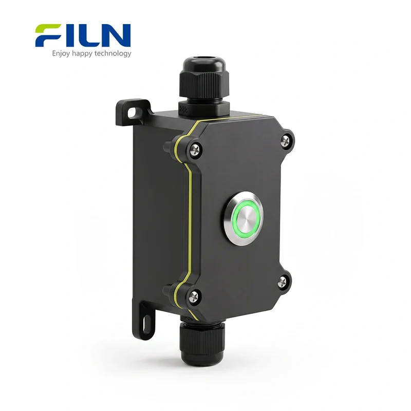 PromotionPush Button Switch Junction BoxJunction Boxes Electrical with 20A Metal Push Button Switch Waterproof IP65 FILN Factory Custom3,14 €
6,01 €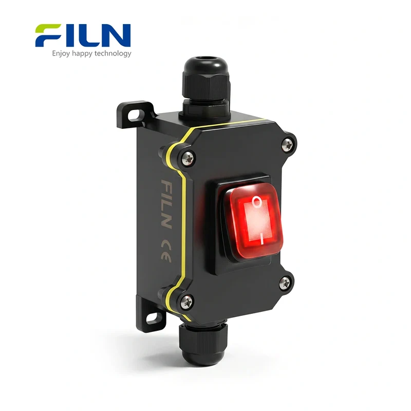 PromotionKCD4 Junction BoxOutdoor Junction Box with KCD4 Rocker Switch 30A High Current IP65 Waterproof FILN2,92 €
4,79 €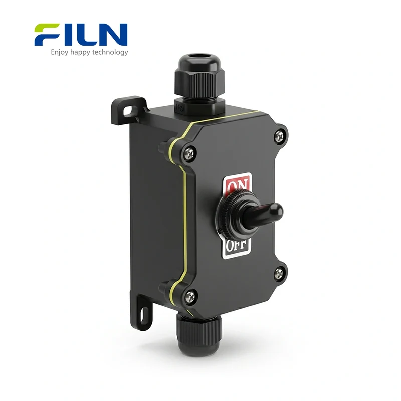 PromotionToggle Switch Junction BoxWaterproof Junction Boxes Electrical with Toggle Switch 12mm SPST SPDT ON-OFF/ON-OFF-ON FILN2,04 €
3,04 €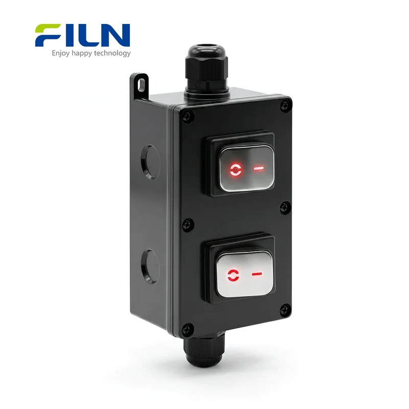 PromotionKCD4 Junction BoxElectrical Outdoor Junction Box Waterproof 30A Stainless Steel KCD4 Rocker Switch FILN4,35 €
6,27 €